
4840 John Deere Hydraulic Pump Diagram Free Download Wiring Diagram Schematic
system,observeutmostcleanlinesswhen workingonhydraulicsystems. E50093—UN—08AUG01. Hydraulic Connections, Hoses, Valves and Parts Author: Industrias John Deere S.A. de C.V. Subject: 440R and H180 Loaders Keywords: BW16220 / BW16221 / BW16414 Created Date:

Schematic Hydraulic System The Wiring Diagram
John Deere 318 User Manual • Legend for hydraulic system schematic—early 318 • John Deere Gardening equipment. Manuals Directory ManualsDir.com - online owner manuals library. Search. Directory. Brands.. LEGEND FOR HYDRAULIC SYSTEM SCHEMATIC—EARLY 318. 1—Hydrostatic Transmission. 10—Variable Hydrostatic. 17—Steering Valve (4.

[Solved!] John Deere Hydraulic System Diagram in 2023
John Deere Lawn & Grounds Care Division F911, F915, F925, F932 and F935 Front Mowers Serial No. (010001— ). Group 10—Hydraulic Lift Cylinders Group 15—Weight Transfer Valve Group 20—Oil Cooler. Group 20—System Schematic Diagram

hydraulic fluid or fluid transmission deere Quotes hydraulic system john diagram
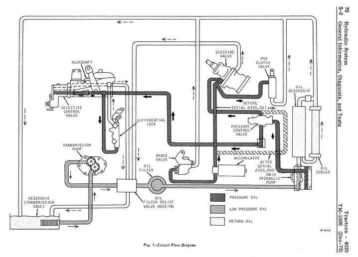
When pressure in hyd system falls springs push pistons back against rotating shaft & pumping oil commences. Pumping is controlled via the stroke control valve. Control valve on 148 loafer mounted on 4020/4230 should be closed center type. Mar 11, 2020 / Hydraulic System on 4230 #7.
[View 27+] Hydraulic Schematic John Deere Hydraulic System Diagram
All relief valves described below operate in the same way. The early model *850 and 950 tractor has one relief valve located in the rockshaft piston cover. If hydraulic oil pressure exceeds 12756-13445 kPa (128-134 bar) (1850-1950 psi), the valve opens and relieves oil to sump. Late model * *850 and 950 tractors have two relief valves.
John Deere Hydraulic System Diagram cloudshareinfo
John Deere Worldwide Commercial and Consumer Equipment Division TM1630 (Apr01) Replaces TM1630 (1Feb98). • System Schematic • Theory of Operation • Troubleshooting Chart • Diagnostics • Tests & Adjustments. bearings, hydraulic seals, fuel injection pumps or other sensitive parts and components may cause product malfunctions. Reduce

John Deere Hydraulic System Q&A, Diagrams & Parts JustAnswer
John Deere Lawn & Grounds Care Division 4200, 4300 and 4400 Compact Utility Tractors. • System Schematic • Theory of Operation • Troubleshooting Chart • Diagnostics • Tests & Adjustments. bearings, hydraulic seals, fuel injection pumps or other sensitive parts and components may cause product malfunctions. Reduce
John Deere Hydraulic System Diagram cloudshareinfo
Illustrated Factory Diagnostic and Repair Technical Manual for John Deere Tractors 5200, 5300, 5400 and 5500 This manual contains high quality images, circuit diagrams, instructions to help you to operate, maintenance, diagnostic, and repair your truc / Deere Technical Manuals. Tests and Adjustments Hydraulic System Operation,.
2040 hydraulics
Allen Edwards is an expert on John Deere tractors. He's worked hands on with them for more than 30 years. In this video he explains the basics of how the hy.

John Deere Hydraulic System Diagram cloudshareinfo
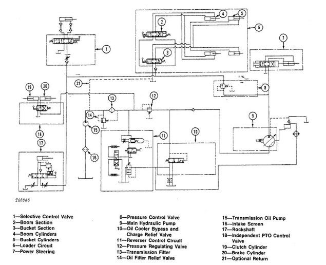
The hydraulic system diagram of a John Deere tractor illustrates the intricate network of hoses, valves, and cylinders that make up the hydraulic system. It shows how hydraulic fluid is circulated, pumped, and controlled to provide the desired hydraulic power to different parts of the tractor.

[DIAGRAM] John Deere Hydraulic Pump Diagram
Illustrated Factory Diagnosis and Tests Service Manual for John Deere Tractors 5220, 5320, 5420 & 5520 This manual contains high quality images, circuit diagrams, instructions to help you to operate, maintenance, diagnostic, and repair your truck. This / Deere Technical Manuals. Tests and Adjustments Hydraulic System Operation,.

John Deere 2755 Hydraulic System Q&A on Problems, Diagrams & Parts JustAnswer
John Deere Hydraulic System Diagram - cloudshareinfo. John deere 7000 planter parts diagram Planter 1770 deere blower john hydraulic valve beyond power series hookup vacuum control parts row 777parts tractors dual systems spare Deere hydraulics troubleshooting spelling. John deere 7000 and 7100 planter

John Deere 4430 Hydraulic Diagram Wiring Diagram
Find parts & diagrams for your John Deere equipment. Search our parts catalog, order parts online or contact your John Deere dealer.

John Deere 4430 Hydraulic Diagram
The John Deere 4440 is a versatile tractor that is equipped with a robust hydraulic system. This system plays a crucial role in operating various implements and attachments, making it an essential component for a range of agricultural tasks. One key feature of the John Deere 4440 hydraulic system is its high capacity.
Hydraulic problem on a 2755
7. Quadrant. John Deere's hydraulic system diagram illustrates the components of the system, including a lever with a knob, push nut, and insert. This combination allows for precise control of the tractor by providing operators with easy access to simple and effective adjustments.

John Deere 318 Hydraulic System Diagram diagramwirings
Winch. The diagram shows a winch powered by a hydraulic motor. The directional control valve with built-in relief features optional flow control to control the speed of the winch . The hydraulic pump and motor must be matched to the torque requirements of the winch.
- Off White Air Jordan 4
- Attractive Meaningful Small Upper Back Tattoos For Guys
- First Day Of School Balloons
- Cornet Brass Instruments For Sale
- Qr Codes On Gravestones Uk
- Strong Days Ahead Hair Kit
- Fiat 500 Front Shock Absorber
- Zak Mir Bulletin Board Heroes
- How To Obtain Sc Clearance
- Squier Strat Classic Vibe 50