Hvac Training on Electric Heaters HVAC Training for Beginners
Operation - Hot water only. Power starts at terminal 3 (HW On) in the programmer. This passes via the wiring centre terminal 6 to the cylinder thermostat. If heat is required, power continues to terminal 8 in the wiring centre, and on to the boiler and pump. The valve is not powered at all, and the spring holds it in position B, so water from.
heating system blog All Star Systems
S Plan Wiring Diagram. S Plan wiring diagrams for fully pumped central heating and hot water systems with pump overrun, includes connections for the boiler, hot water and central heating valves, tank stats, central heating wiring centre and room stats. Scroll to the bottom to download the s plan wiring diagram pdf.

Radiant / baseboard mechanic room piping layout / design — Heating Help The Wall
What is a Y plan heating system & how does it work? In this guide we explain it all, as well as potential limitations.
Rheem Residential Electric Water Heater Wiring Diagram Database Wiring Diagram Sample
The following guide illustrates how Wundafloor warm water underfloor heating systems can be coupled together with the majority of central heating plumbing and control systems. The majority of modern central heating systems make use of motorised valves, often called Zone valves, to divide different heating systems and hot water generation ie.
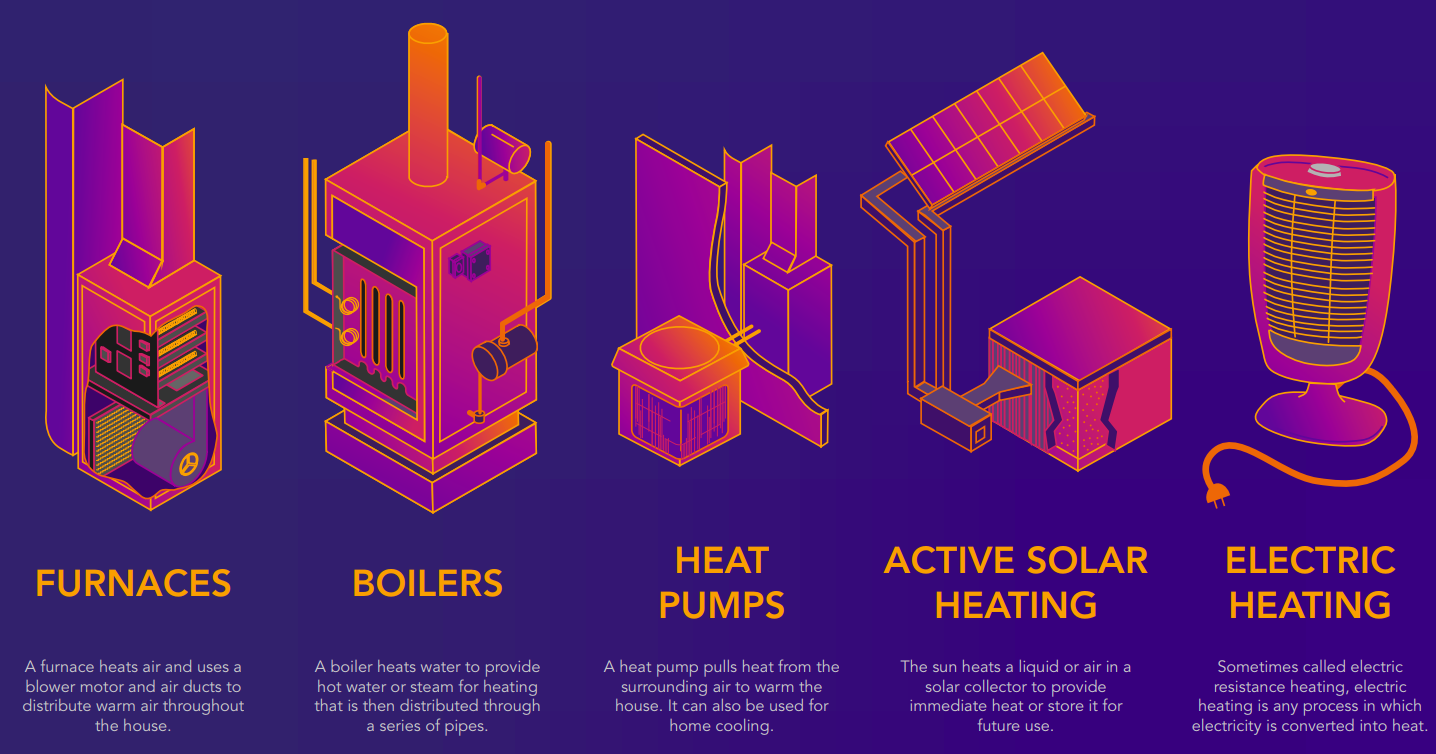
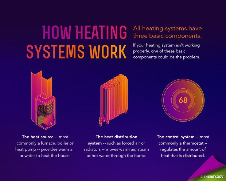
What Type of Heating System do I have in my Home?
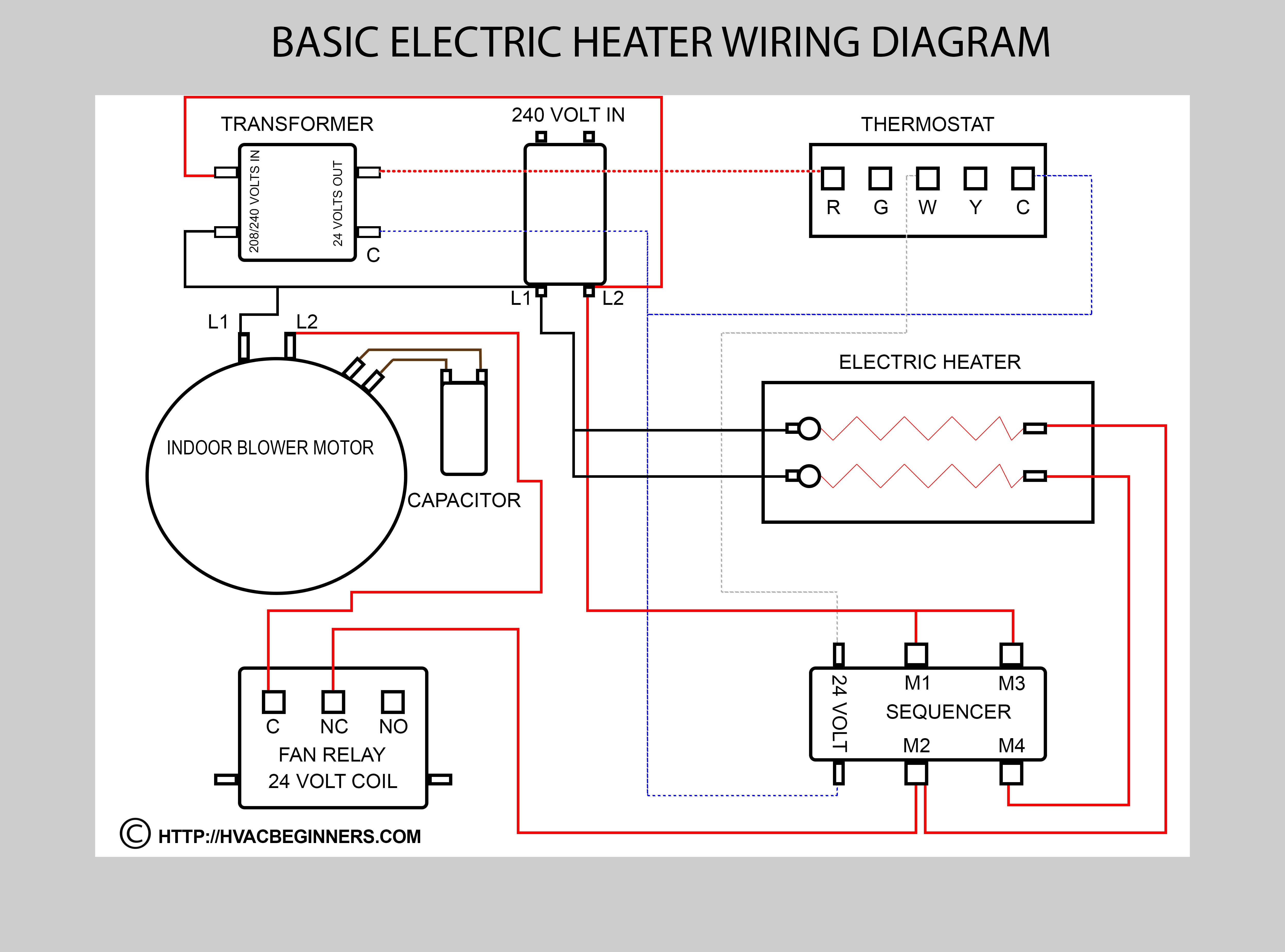
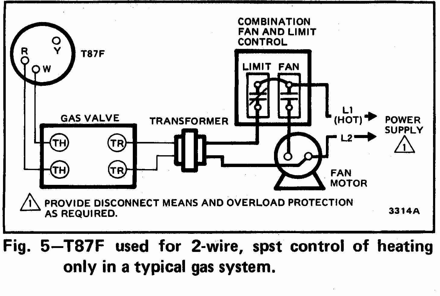
The control wiring diagram includes: Power supply connections: The diagram shows how the system is connected to the electrical power source, including the main voltage and ground connections. Control devices: It illustrates the various control devices used in the HVAC system, such as thermostats, pressure switches, relays, and contactors.

The Heat Exchanger System Diy Radiant Floor Heating Radiant throughout Domestic Hot Water
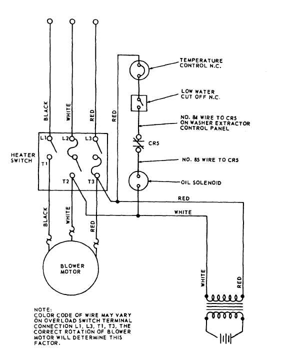
These consist of red, white, green, and blue wire. While the red and white wires control power and heating, the green wire controls fans, and the blue "C" or "B" are either your common wire or for your heat pump. Five wires. The most common wiring system usually features five wires. These include red, white, blue, green, and yellow wire.

Nirvana Heat Pump Wiring Diagram Wiring Diagram For Rheem Heat Pump Contacter MiniSplit Heat
System Wiring Diagrams . Y Plan System Schematic . Showing flow from boiler, to Y Plan, or Mid Position Diverter Valve, and then onto heating or hot water circuit.. C Plan Schematic . Gravity hot water controlled by a 6 wire valve (not your standard 5 wire valve) and a pumped central heating circuit controlled by a thermostat. C Plan Wiring.

Wiring Diagram — Heating Help The Wall
A house heating system diagram is a visual representation of how a heating system in a house functions. It provides a clear overview of the various components and their connections, allowing homeowners to better understand how their system works and make informed decisions about maintenance and repairs. One of the key components in a house.
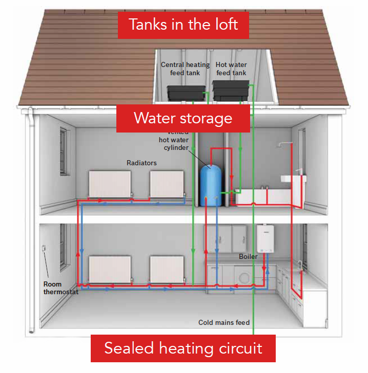
Central Heating Systems Explained by Mr Central Heating! Mr Central Heating Blog
Install the Heater. Strip 5/8 in. of insulation from each wire's end, then connect the black and taped white wires to the black heater wires using wire connectors. Connect the cable's bare ground wire to the green heater ground wire. Push the heater into the can and fasten it. Install the cover grille.
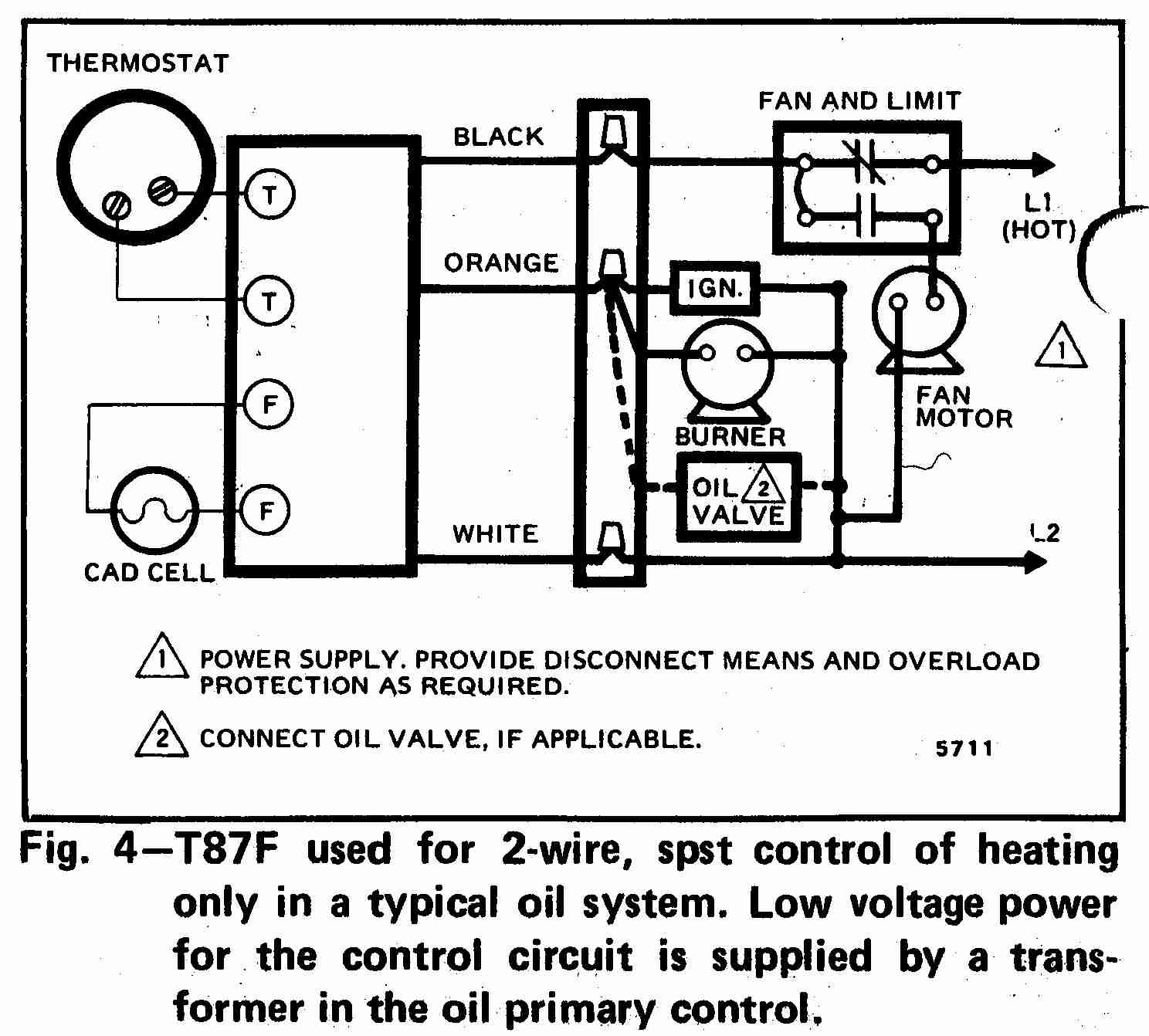
Room thermostat wiring diagrams for HVAC systems
G wire (fan) connected to the fan control to operate a blower in your HVAC system. Y1 wire (cooling) connected to the compressor/refrigerant system. Y2 wire (second stage cooling) connected to the 2nd stage cooling system. C wire (common) wire to complete the circuit and keep power flowing.

Hot Water Boiler Heating System Diagram General Wiring Diagram
The diagram set includes wiring plans for a number of popular configurations of central heating systems, C Plan, W Plan, Y Plan, S Plan, S Plan+ etc. and you should select the most appropriate diagram that matches the components you have installed in your system along with what you're hoping to achieve in terms of controllability. Obviously.
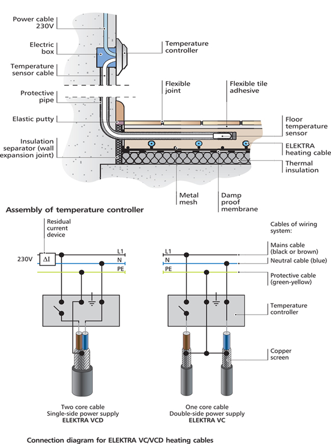
Wiring Diagram Underfloor Heating Home Wiring Diagram
Understanding the wiring diagrams for an S Plan heating system is crucial for anyone involved in installation, maintenance, or troubleshooting. These diagrams provide a visual representation of the various components and their interconnections, helping you to identify potential issues and make necessary adjustments. 2.

Wiring Diagram For 2 Zone Heating System Electrical Schematic Diagram Guide
Most baseboard heating systems use 240-volt circuits, but 120-volt heaters are also available, as they are often used to provide supplemental heat in individual rooms that are also served by a central heating system.. Carefully read the wiring diagram and ensure you identify the wire leads marked "Line" and "Load" before beginning. "Line.
Electric Heater Wiring Diagram Thermostats Waterheatertimer 220v Wiring Diagram 240 Volt
S Plan heating systems need to have a nice neat wiring center to enable everything from the plumbing up to work properly! I show you what the wires do and ho.

Clitech EVI heat pumps water system installation instruction
In this LearnElectrics video we will look at the wiring method of the Y Plan central heating system.This follows on from a previous video that looked at the.
Heating system wiring diagram DIYnot Forums
This video covers the wiring and electrical operation of an S plan system with two 2-port valves. Wiring diagrams and further information continues below. View on Youtube. System Wiring. This diagram shows the wiring layout using the most typical components. Here, coloured wires indicate the permanent mains supply to the boiler and programmer.